How to Configure an Injection Molding Machine for Different Applications
Abstract:
Learn how to configure an injection molding machine around the part, resin, mold, and output. Compare clamping force, shot capacity, temperatures, filling, cooling, and machine types for packaging, medical, automotive, electronics, and insert molding.
An injection molding machine should be configured around the part—not around a familiar machine size or a previous job. The correct setup depends on the resin, mold, quality requirements, and production target.
Configuration has two stages: select equipment with suitable clamping force, mold space, injection capacity, controls, and auxiliary interfaces; then establish a stable process using the right temperatures, speeds, pressures, transfer points, and cooling conditions.
1. Collect the Application Data
Before comparing machines, prepare the information that determines whether a machine can run the mold safely and consistently.
| Area | Information to collect |
| Part | Dimensions, weight, projected area, wall thickness, tolerances and appearance requirements |
| Mold | Cavities, runner type, mold size and weight, thickness, opening and ejector stroke |
| Resin | Exact grade, density, processing range, drying needs and filler content |
| Production | Target cycle, annual volume, shifts and automation level |
| Quality | Critical dimensions, weight tolerance, traceability and cleanliness |
| Utilities | Power, cooling water, compressed air, space and material handling |
Do not select a machine by industry label alone. A small automotive connector and a large bumper belong to the same industry but require very different machines.
2. Select the Machine Architecture
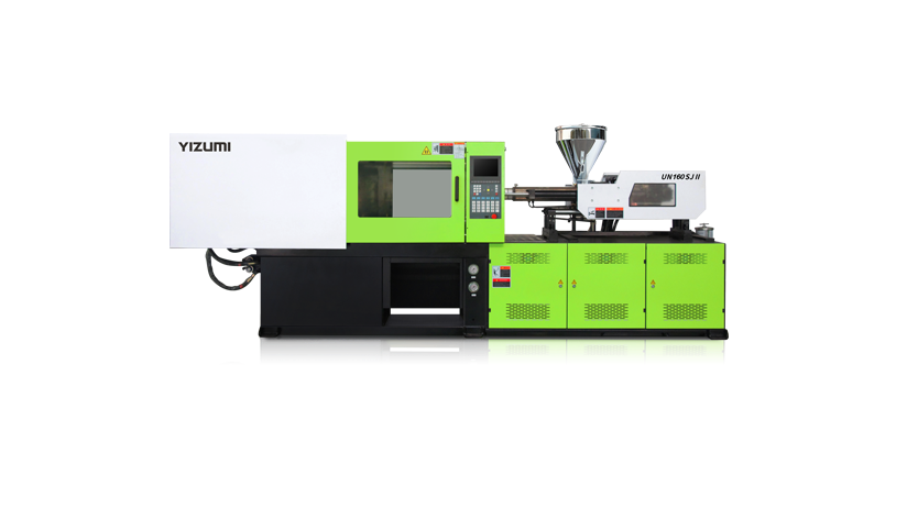
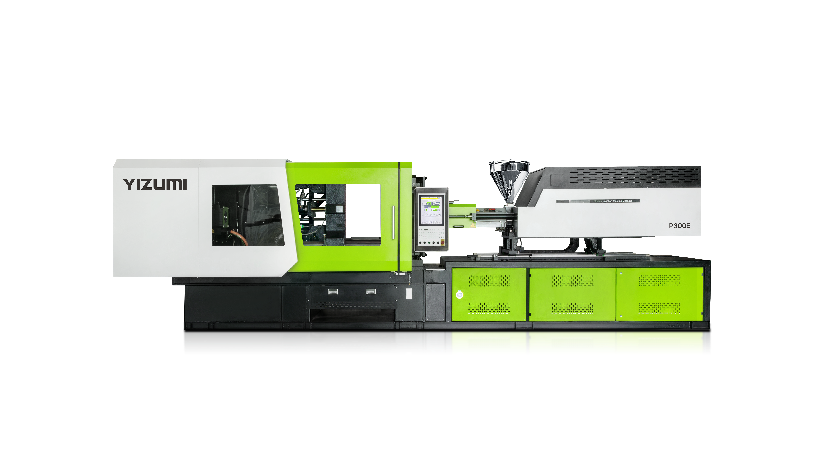
Servo-hydraulic Injection Molding machines suit general production, larger parts, and molds with complex hydraulic movements.
Electric Injection Molding machines are useful when repeatable movement, accurate pressure control, clean operation, and low noise are priorities. These requirements are common in medical, electronics, and other precision applications.
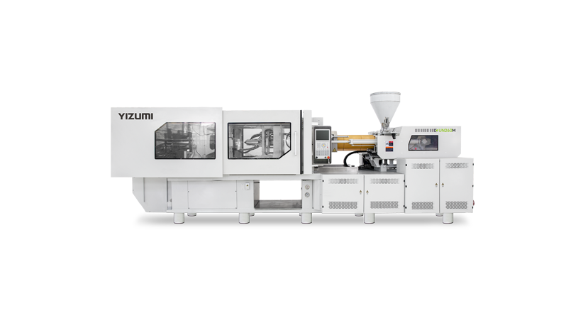
Two-platen Injection Molding machines are often considered for large automotive, appliance, logistics, and industrial parts. With large molds, platen size, opening stroke, mold weight, and robot access may be as important as tonnage.
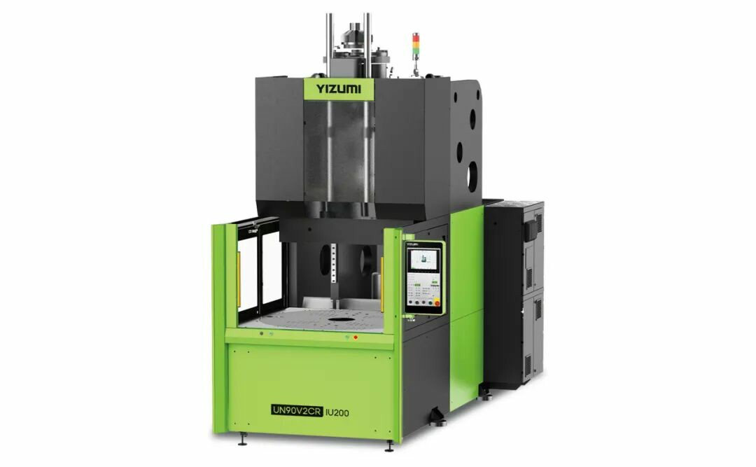
Vertical Injection Molding machines can simplify insert loading because the mold arrangement helps keep terminals, cables, or metal inserts in place. Multi-component machines are needed when two colors or materials must be molded in a controlled sequence.
YIZUMI's FF series uses closed-loop injection pressure control, with stated injection and holding-pressure stability of ±0.1 MPa. This matters when small filling or packing changes affect dimensions or weight.
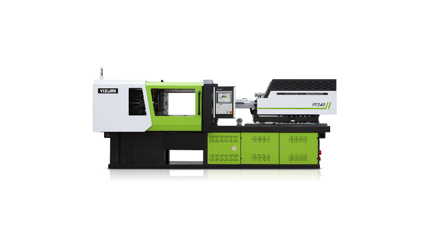
FFSeriesElectricInjectionMoldingMachine
3. Calculate Clamping Force
Clamping force keeps the mold closed against pressure inside the cavities.
Required clamping force (kN) = total projected area (cm²) × estimated cavity pressure (MPa) × 0.1
If a four-cavity part and runner system has a projected area of 600 cm² and the estimated cavity pressure is 35 MPa: 600 × 35 × 0.1 = 2,100 kN
After adding an engineering margin, a machine around 2,300–2,500 kN may be evaluated.
This is a screening calculation. Actual pressure changes with resin viscosity, wall thickness, flow length, gate design, mold temperature, and injection speed. Simulation and trials should confirm the final requirement.
Also check platen dimensions, tie-bar spacing, mold thickness, mold weight, opening stroke, ejector capacity, core pulls, nozzle radius, and locating ring. A machine may provide enough force but still be unsuitable because the mold cannot fit, open, or eject correctly.
4. Match the Injection Unit
Calculate the total shot: Total shot weight = part weight × cavity count + runner weight
For four 52 g parts with an 18 g runner: 52 × 4 + 18 = 226 g
If machine capacity is stated using polystyrene as the reference material, convert it for the production resin’s density.
The injection unit must provide:
· Enough pressure to maintain the required filling speed
· Sufficient injection rate for the wall thickness and flow length
· Plasticizing output that completes recovery within the cycle
· Stable cushion and check-ring performance
· A screw design suitable for the resin
· Acceptable material residence time
An oversized barrel is not automatically safer. A small shot may remain in it too long, causing degradation or viscosity changes.
Filled materials may require wear-resistant screws and barrels, while heat-sensitive or corrosive compounds may need dedicated components.
5. Set Temperatures From the Resin Grade
Use the processing data for the exact resin grade. For example, gives melt-temperature ranges of about 190–205°C for some softer grades and 215–235°C for harder grades. It also recommends checking actual melt temperature rather than relying only on the controller display.
Confirm the barrel profile, actual melt temperature, mold-temperature range, drying conditions, residence-time limit, screw speed, and back pressure.
Mold temperature is a quality setting. It affects flow, surface replication, shrinkage, crystallinity, warpage, dimensions, and cycle time.
Confirm coolant flow through every circuit. The correct setpoint cannot compensate for a blocked channel, incorrect hose connection, or undersized temperature-control unit.
6. Establish Filling and Packing
Use a controlled injection-speed profile rather than maximum pressure to force the cavity full. A practical profile may use:
· A controlled speed through the gate
· Faster filling through the main cavity
· A slower final filling stage
· Transfer to holding pressure before full packing
Pressure should provide enough reserve to maintain the selected speed. If the machine reaches its pressure limit immediately, inspect melt temperature, gate size, venting, wall thickness, and injection-unit capacity before increasing pressure.
Holding pressure compensates for shrinkage until the gate seals. Determine holding time with a gate-seal study: increase the time in small steps and record part weight. Once weight stops increasing, further holding time generally adds no useful packing.
Excessive packing can cause flash, stress, and difficult ejection. Insufficient packing can cause sink marks, voids, and dimensional variation.
Use only enough back pressure to create a uniform melt. Excessive back pressure increases shear heat, recovery time, fiber damage, and wear.
7. Configure for the Application
| Application | Main machine priorities | Main process priorities |
| Thin-wall packaging | High injection rate, fast response, rigid clamping | Fill speed, cooling balance, short cycle |
| Medical products | Repeatability, clean design, process records | Stable pressure, traceability, controlled handling |
| Large automotive parts | Mold space, clamp force, opening stroke | Warpage control, cooling balance, automation |
| Precision electronics | Accurate position and pressure control | Small-shot stability, appearance, dimensions |
| Insert molding | Vertical layout, mold protection, insert detection | Loading repeatability and safe handling |
| Multi-component parts | Multiple injection units and accurate indexing | Bonding, sequence control and balanced cooling |
Thin-Wall Packaging
Thin-wall containers, lids, and closures need high injection rate and rapid response. Cooling and part removal can be as important as filling.
YIZUMI's PS5 Injection Molding Machine platform is designed for low-pressure, high-speed injection and compound movements for thin-wall products. Results still depend on mold cooling, hot-runner balance, material delivery, robot speed, and downstream handling.
A fast injection molding machine cannot compensate for an unbalanced hot runner, restricted cooling channels, or an automation system that cannot match the molding cycle.
Medical Products
Medical molding places greater emphasis on repeatability, cleanliness, process records, and controlled handling.
The FF-M series electric medical Injection Molding machine has stated injection and holding-pressure stability of up to ±0.1 MPa, and YIZUMI reports a 0.125 ms control cycle. These values must still be considered with mold performance, material control, and process validation.
A suitable medical production cell may also require closed material conveying, controlled drying, automated removal, reject separation, process-data recording, and cleanroom-compatible equipment.
Automotive and Large Parts
Large automotive parts may require high clamping force, but mold dimensions, opening stroke, core movements, robot access, and the part-removal path also shape the machine choice.
For visible trim and large panels, balanced cooling and packing are often more useful than higher pressure. Uneven mold temperature can cause warpage even when the machine has more than enough clamping force.
Large molds may therefore benefit from a two-platen injection molding machine that provides sufficient mold space and opening travel without relying only on a larger nominal tonnage.
Precision Electronics
Connectors, housings, switches, and other precision parts need stable transfer, consistent cushion, accurate mold protection, and controlled material preparation.
Avoid placing very small shots in unnecessarily large barrels. Long residence time can create material degradation and process variation even when the machine can easily provide the required injection pressure.
Insert and Multi-Component Molding
Insert molding requires insert detection, repeatable loading, mold protection, and safe access. A vertical injection molding machine can make manual or automated insert positioning easier, but the complete process must also prevent missing, displaced, or incorrectly oriented inserts.
For two-color or hard-soft products, confirm:
· Material compatibility
· Injection-unit orientation
· Mold indexing accuracy
· Injection sequence
· Bonding conditions
· Cooling balance between materials
8. Validate Before Production
A setup is not complete when the first acceptable part appears. It is complete when the process repeatedly produces acceptable parts within a defined window.
Use this sequence:
· Run a short-shot study to observe filling
· Stabilize fill time
· Set the injection-to-holding transfer point
· Perform a gate-seal study
· Check cushion and screw recovery
· Record actual melt and mold temperatures
· Measure part weight and critical dimensions
· Define approved operating limits
· Save a controlled setup record
The record should include the machine, screw, mold, resin, dryer settings, process values, and quality results.
Process monitoring should focus on actual results, not only controller setpoints. Useful indicators include:
· Fill time
· Transfer position
· Peak injection pressure
· Cushion
· Screw-recovery time
· Part weight
· Cycle time
· Critical dimensions
For energy comparisons, use a defined method. EUROMAP 60.1 assesses machine-related efficiency through specific energy consumption in kWh/kg and idle power under stated test cycles. This is more useful than isolated percentage claims from unrelated conditions.
Common Configuration Mistakes
· Selecting a machine by clamping tonnage alone
· Copying settings from another machine without conversion
· Using maximum pressure to hide gate, venting, or temperature problems
· Ignoring dryer, chiller, mold-temperature controller, or robot capacity
· Changing several parameters at the same time
· Reducing cycle time before quality is stable
· Recording setpoints but not actual process values
· Bypassing guards or safety interlocks
ISO 20430:2020 defines essential safety requirements for injection molding machines and provides information for safe use. Setup and maintenance should be performed by trained personnel under the manufacturer’s procedures and local rules.
Conclusion
Configuring an injection molding machine starts with the part, resin, mold, and production targets. Select machine type, clamping force, mold space, shot capacity, screw, and auxiliaries to suit the application. Set temperatures from the resin grade, then optimize injection speed, pressure, holding, cooling, and recovery. Packaging needs speed and cooling; medical and electronics need repeatability; large automotive parts need mold space and stable clamping. Validate the setup before production.
FAQ
Q1. Can One Injection Molding Machine Run Different Applications?
A: Yes, if its clamping force, mold space, injection unit, controls, and auxiliary interfaces cover every mold.
A general-purpose machine may still lack the injection speed, cleanliness, mold space, or multi-component functions required by a specialized application.
Q2. Should Injection Pressure or Speed Be Adjusted First?
A: Build a controlled speed profile first and provide enough pressure reserve to maintain it.
If pressure reaches the limit too early, check material temperature, gate size, venting, wall thickness, and machine capacity before increasing the pressure setting.
Q3. What Information Is Needed to Select a Machine?
A: Prepare the part drawing, resin grade, shot weight, cavity count, projected area, mold size and weight, target cycle, annual output, and quality requirements.
This allows the machine supplier to evaluate clamping force, injection capacity, mold fit, plasticizing output, and auxiliary equipment together.
Q4. How Can Process Stability Be Checked?
A: Track fill time, transfer position, peak pressure, cushion, recovery time, part weight, actual temperatures, cycle time, and critical dimensions.
Stable panel settings alone do not prove that the molding process is stable.