How to Design an Injection Molding Machine Production Cell
Abstract:
A successful injection molding production cell requires more than automation equipment. Discover how machine selection, mold design, robotics, inspection and MES integration work together to achieve stable cycles, consistent quality and efficient manufacturing.
A reliable injection molding production cell is more than an injection molding machine combined with a robot. It is a coordinated system where the machine, mold, material handling, end-of-arm tooling, inspection equipment and downstream processes work together to achieve stable and efficient production.
When designing a new production cell, the key question is not: "How much automation can be added?" The more important question is:
"How can the production cell consistently produce qualified parts at the required cycle time while maintaining flexibility, reliability and reasonable operating costs?"
The answer starts with understanding the part requirements, mold design and production goals—not simply choosing a robot model or selecting a machine based only on clamping force.
A well-designed injection molding production cell balances three essential elements:
· Process stability: ensuring the injection molding machine and mold deliver consistent part quality.
· Automation efficiency: ensuring robots, tooling and auxiliary equipment support the required production rhythm.
· Quality control and traceability: ensuring every part meets specifications and production data can be monitored and managed.
By designing the entire system as one integrated solution, manufacturers can reduce production risks, improve efficiency and build a production cell that is ready for future expansion.
Start with the Part, Mold and Output Target
Before choosing any equipment, define the conditions the complete cell must meet:
· Part dimensions, projected area and weight
· Resin type and drying requirements
· Number of cavities
· Mold dimensions and weight
· Target cycle time
· Annual production volume
· Dimensional and cosmetic requirements
· Insert loading, assembly or packaging operations
· Required traceability
· Planned changeover frequency
This information determines the injection unit, clamping unit, robot payload, gripping method, inspection technology and cell layout.
A common mistake is to select the injection molding machine first and design the surrounding equipment later. That approach can result in insufficient mold clearance, slow robot entry, limited ejector access or an injection unit that cannot recover material within the cooling time.
Match the Injection Molding Machine to the Mold
The Injection Molding machine is the process foundation of the production cell. If injection, plasticizing, mold movement or ejection is unstable, downstream automation will reproduce that instability more consistently.
Check more than clamping force
Machine selection should include:
· Required clamping force
· Platen size and tie-bar spacing
· Minimum and maximum mold thickness
· Mold-opening stroke and daylight
· Mold weight
· Ejector stroke and force
· Shot size and screw diameter
· Plasticizing capacity
· Hydraulic core-pull requirements
· Robot access between the platens
Shot size should include the combined weight of the molded parts, runners and process allowance. Plasticizing capacity must also be sufficient to prepare the next shot before cooling and part removal are complete.
Select the machine architecture by application
| Application | Typical Machine Priority | Cell Design Priority |
| Precision electronics | All-electric control and repeatability | Part protection, inspection and fast changeovers |
| Medical products | Clean handling and process stability | Traceability, enclosed removal and validation |
| Thin-wall packaging | Fast injection and short dry cycle | Rapid take-out, stacking and packaging |
| Automotive parts | Large mold space and rigid platens | Large robots, mold changes and downstream finishing |
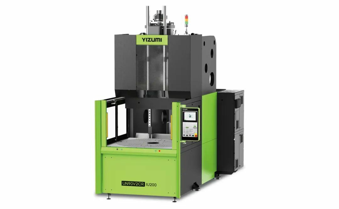
| Insert molding | Accessible or vertical mold area | Accurate insert loading and presence detection |
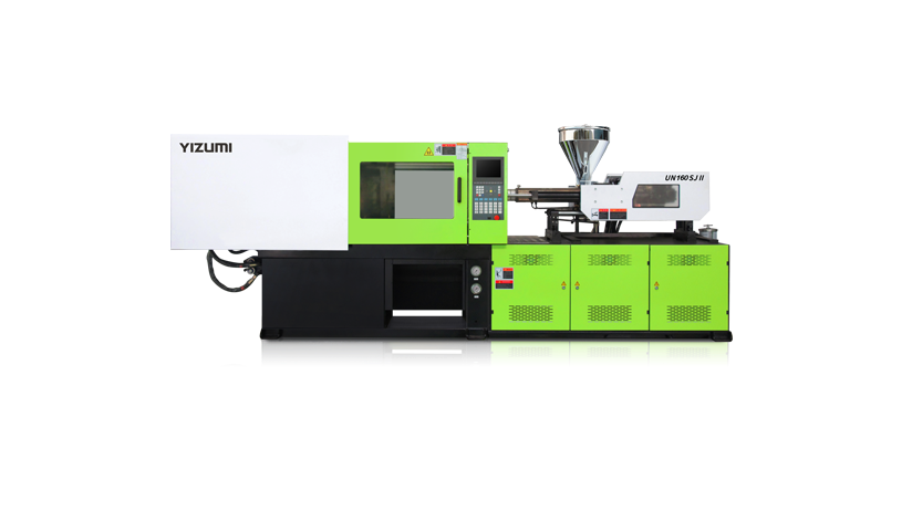
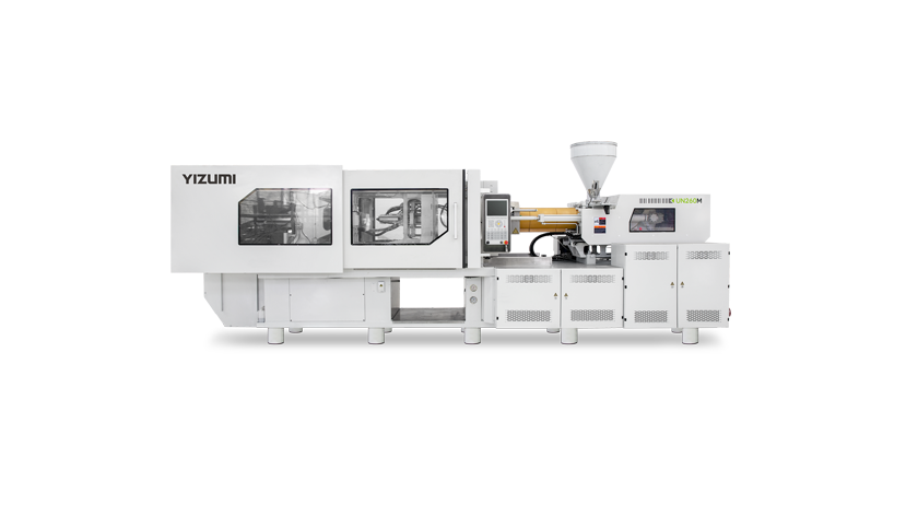
Machine performance should be evaluated in the context of the actual process. For example, the YIZUMI FF Series Injection Molding Machine provides ejector-position accuracy of up to 0.2 mm, supporting repeatable part release and synchronized ejection functions. For large-part applications, the D1-N two-platen series specifies injection-end-position repeatability up to ±0.2 mm and part-weight repeatability of no more than 3‰ under defined conditions.
These values matter because a production robot needs the part to appear in a predictable location on every cycle.
Design the Mold for Automation
Automation problems often begin inside the mold. A part that sticks unpredictably, rotates during ejection or has no accessible gripping surface will be difficult to automate, regardless of robot speed.
An automation-ready mold should include:
· A clearly defined part-retention side
· Sufficient draft and balanced ejection
· Stable gripping or vacuum locations
· Clearance for the robot and end-of-arm tooling
· Sensors confirming ejector and core positions
· Part-presence or removal confirmation
· Organized hot-runner, water and electrical connections
· Permanent mold and cavity identification
For multi-cavity production, cavity identification should remain connected to each part or handling position. Depending on the product, this can be achieved through molded cavity numbers, data matrix codes, separated conveyor lanes or cavity-specific robot placement.
Quick-change connections can reduce downtime, but only when the full changeover is standardized. Mold clamping, cooling circuits, hot-runner connections, robot tooling, inspection recipes and machine parameters must all be included.
Select the Robot by the Required Work
The number of robot axes is not the first selection criterion. Start by defining what the robot must do.
A simple Cartesian robot may be the most efficient choice for fast vertical entry, part removal and conveyor placement. A six-axis robot becomes more useful when the cell requires complex orientation, insert loading, visual presentation, assembly or packaging.
Robot selection should consider:
· Part, runner and EOAT weight
· Required reach
· Acceleration with the full payload
· Robot time inside the mold
· Required part orientation
· Number of downstream operations
· Floor and overhead clearance
· Future product families
Design the EOAT around the real part condition
A freshly molded part may still be warm, flexible and dimensionally unstable. Excessive vacuum or gripping force can leave marks or cause deformation.
An effective EOAT may combine:
· Vacuum cups for broad, cosmetic surfaces
· Mechanical fingers for positive retention
· Sensors confirming part pickup
· Separate runner gripping
· Insert-loading fixtures
· Quick-change connections
· Tool-identification sensors
The best gripping test is not performed on a cold sample at a workbench. It should be performed at the real mold-release temperature, actual cycle time and production speed.
Protect the Cycle Time
The robot’s catalogue speed does not determine cell output. The most important automation measurement is usually robot in-mold time: the period between the robot entering the mold area and clearing it so the next mold-close command can begin.
Create a timing study that separates:
· Mold opening
· Robot entry
· Ejection and gripping
· Robot exit
· Mold closing
· Inspection
· Assembly or packaging
Whenever possible, inspection and secondary processing should continue while the next molding cycle is running.
If a vision inspection takes longer than the molding cycle, consider:
· Two inspection stations
· A rotary indexing table
· Multiple parts inspected in one image
· A buffer conveyor
· Parallel robots
· Offline inspection for selected features
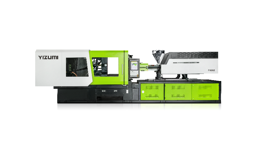
For high-speed applications, machine motion must also support the cell target. YIZUMI's P-E high-speed Injection Molding Machine models specify a dry cycle of approximately 2–3.6 seconds and energy savings of 30–50% compared with standard models under applicable operating conditions. Such performance is useful only when take-out, cooling and downstream handling can keep pace.
Use Inspection to Control Risk, Not to Hide an Unstable Process
Inline inspection should be selected according to the defect and the consequence of escape.
| Inspection Method | Suitable Checks | Main Limitation |
| Machine-process monitoring | Pressure, position, time and temperature | Does not directly see every product defect |
| Cavity-pressure sensing | Filling and packing behavior | Requires mold sensors and process validation |
| 2D vision | Presence, color, flash, short shots and orientation | Limited visibility of hidden or three-dimensional features |
| 3D vision or laser | Height, profile and surface form | Higher cost and longer processing time |
| Weight checking | Missing material and process variation | Cannot identify the defect location |
| Functional testing | Leakage, electrical or assembly function | Can become the cycle bottleneck |
Artificial intelligence is not automatically the best inspection method. When defect examples are rare, lighting changes or product variants are frequent, a carefully controlled rule-based vision system may be easier to validate and maintain.
The reject process must also be engineered. A production cell should confirm that a rejected part reached the reject container, prevent operators from mixing rejected and accepted products, and retain the inspection result with the corresponding cycle or cavity.
Avoid These Production Cell Design Mistakes
The most common failures are usually caused by project sequencing rather than individual equipment quality:
1. Selecting the machine before confirming the mold and shot requirements
2. Designing the mold without robot-access review
3. Choosing a robot only by payload or axis count
4. Ignoring robot in-mold time
5. Adding vision inspection without defining defect samples
6. Failing to design a verified reject path
7. Allowing multiple suppliers to leave interface responsibility unclear
8. Forgetting mold-change and maintenance access
9. Connecting MES without defining required data fields
10. Accepting the cell without measurable FAT and SAT criteria
Before releasing a purchase order, assign one responsible party for complete cycle performance, machine–mold compatibility, safety integration and final production acceptance.
What to Include in a Production Cell RFQ
A useful RFQ should provide enough information to engineer the complete system:
· Part drawing and 3D model
· Material specification
· Part and shot weight
· Number of cavities
· Mold dimensions and weight
· Target cycle and annual output
· Required machine type
· Insert-loading or downstream operations
· Inspection requirements
· Traceability and MES requirements
· Factory water, power, air and network conditions
This prevents suppliers from quoting technically different solutions against the same project.
FAQ
Q1. What is an Injection Molding Machine Production Cell?
A: An injection molding machine production cell is a complete manufacturing system that integrates the injection molding machine, mold, robot, auxiliary equipment, inspection system and production management software. Unlike a standalone machine, a production cell is designed around the complete manufacturing process to achieve stable cycle time, consistent quality and efficient production.
Q2. How Do I Choose the Right Injection Molding Machine for an Automated Production Cell?
A: The right injection molding machine should be selected based on the part, mold and production requirements rather than clamping force alone. Important factors include shot size, plasticizing capacity, mold dimensions, tie-bar spacing, cycle time, material requirements and automation needs. A suitable machine provides stable molding performance and creates a reliable foundation for robots, inspection systems and downstream processes.
Q3. How Can I Reduce Cycle Time in an Injection Molding Production Cell?
A: Reducing cycle time requires optimizing the entire production system, not only increasing injection speed. Manufacturers should evaluate mold cooling efficiency, plasticizing capacity, robot in-mold time, part removal methods and downstream processes. In many applications, improving robot movement, parallel inspection and mold design can reduce overall cycle time while maintaining part quality.
Q4. When Should an Injection Molding Production Cell Use Vision Inspection?
A: Vision inspection is recommended when product quality requirements, production volume or traceability needs exceed manual inspection capability. It can help detect issues such as missing parts, incorrect assembly, surface defects and dimensional variations. However, inspection should support a stable molding process rather than replace proper machine and mold optimization.
Build the Cell Around Qualified Output
A successful injection molding machine production cell is not the one with the highest robot speed or the greatest number of connected devices. It is the system that produces the required number of qualified parts with predictable cycle time, manageable maintenance and clear responsibility.
YIZUMI combines injection molding machines, robotic automation, intelligent manufacturing and application engineering. Its equipment portfolio covers electric, high-speed, two-platen, multi-component, vertical and application-specific machines. YIZUMI more than 140,000 machines operating successfully, more than 5,000 employees and average annual R&D investment exceeding CNY 200 million.
Planning a new production cell? Submit your part weight, material, mold dimensions, target cycle time and automation requirements for an injection molding machine configuration review.