Packaging Injection Molding: What the Machine Must Do Beyond High Speed
Abstract:
Packaging injection molding requires more than speed. Stable V/P control, balanced clamping, consistent plasticizing and cooling, synchronized automation, and energy per good part determine reliable output, lower costs, and longer mold life at scale.
Speed matters in packaging injection molding. Thin walls, long flow paths, multi-cavity molds and short production cycles all require the melt to enter the cavity quickly. But maximum injection speed is only one part of the result.
A packaging injection molding machine must also decelerate accurately, switch from filling to holding pressure at the correct moment, keep the mold evenly closed, prepare the next shot without delaying the cycle, and synchronize with labeling, take-out and inspection equipment.
For packaging manufacturers, the most useful question is therefore not: "How fast can the machine inject?" It is: "How many conforming parts can the complete molding cell produce per hour, with stable quality, controlled energy use and acceptable mold wear?"
The Short Answer: Six Capabilities Beyond High Speed
A production-ready packaging injection molding machine should provide:
· Stable injection acceleration and deceleration;
· Accurate velocity-to-pressure switchover;
· Rigid and evenly distributed clamping force;
· Consistent plasticizing and thermal control;
· Synchronized mold movement, ejection and automation;
· Process data that proves repeatability and cost per good part.
These capabilities must work together. A fast injection unit cannot compensate for unstable clamping, slow material recovery, poor mold cooling or delayed robotic handling.
1. High Speed Must Remain Controllable
Thin-wall packaging requires rapid filling because the melt begins cooling as soon as it contacts the mold surface. The machine needs enough injection rate and pressure reserve to fill the cavity before the flow front freezes.
The critical moment, however, often occurs near the end of filling.
In many decoupled molding processes, the machine changes from velocity-controlled filling to pressure-controlled packing when the cavity is approximately 95–98% volumetrically filled. This is a starting principle rather than a universal fixed value. The correct transfer point must be verified for the material, part geometry, gate design, hot runner and process window.
Switch too early and the machine may struggle to complete the final flow path, producing short shots or weak features. Switch too late and melt momentum can create a pressure peak, flashing the parting line or placing unnecessary stress on the mold. Research on switchover control confirms that late transfer can increase pressure peaks and required clamping force.
The buyer should therefore look beyond maximum screw speed and ask the supplier to demonstrate:
· Fill-time repeatability;
· V/P transfer position;
· Peak injection pressure;
· Cushion consistency;
· Part-weight variation;
· Cavity-to-cavity balance;
· Stability over an extended automated run.
For applications requiring highly responsive process control, the YIZUMI P-E Series High-speed injection molding machines uses closed-loop injection-pressure control with published pressure stability of ±0.02 MPa. Its controller provides a 1 ms scan cycle, Statistical Process Control and process-curve recording, helping operators identify small changes before they become visible defects.
This is the difference between reaching a high speed once and repeating a stable process throughout production.
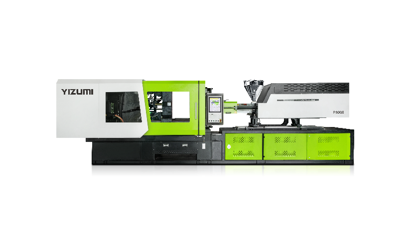
YIZUMI P-E Series High-speed injection molding machines
2. Clamping Stability Is More Than Maximum Tonnage
Packaging molds can generate high cavity pressure across a large projected area. The clamping system must resist that force without allowing the mold parting line to open.
However, simply choosing more tonnage is not always the right answer.
If clamp force is distributed unevenly, one section of the mold may flash while another is over-compressed. Excessive clamp force can also increase stress on the mold, tie bars and parting surfaces. The goal is not the highest possible setting, but the lowest stable force that keeps the mold sealed and properly supported.
A packaging machine should be evaluated for:
· Platen rigidity under load;
· Platen parallelism;
· Tie-bar force balance;
· Mold-weight support;
· Repeatable mold-open position;
· Sensitive low-pressure mold protection;
· Stability during long-term high-speed movement.
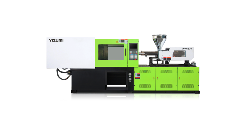
The YIZUMI PS5 Series High-Speed Injection Molding Machines, available with clamping forces from 2,800 to 5,600 kN, uses a reinforced platen optimized through finite element analysis. Its anti-tilt movable-platen support is designed to improve parallelism and reduce tilting when running heavy molds at high speed. The machine also includes intelligent clamping-force management that identifies and optimizes the required clamping parameters.
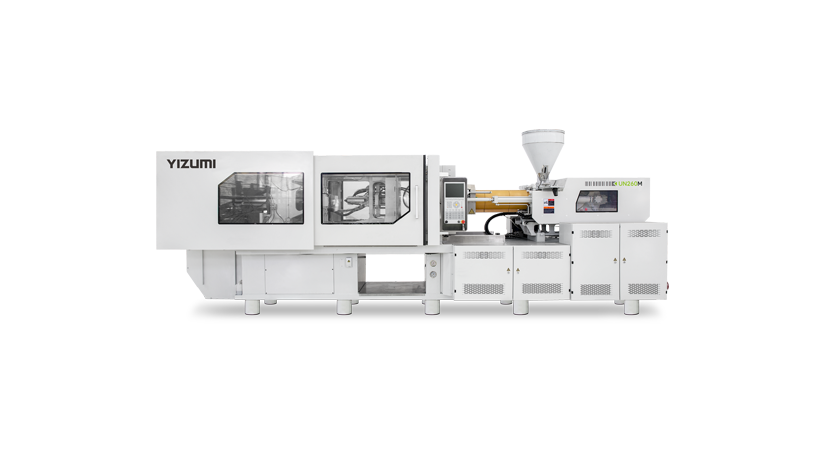
For multi-cavity thin-wall packaging, the P Series covers clamping forces from 150 to 550 T. Its reinforced clamping structure is designed to transfer force toward the platen center and minimize deformation. YIZUMI also reports that its high-speed mold-opening and closing control can increase movement speed by 15–20% while improving end-position repeatability.
These structural details affect part consistency, mold life and the time available for robotic take-out.
3. Plasticizing and Cooling Often Set the Real Cycle
Fast filling receives most of the attention, but it may occupy only a small portion of the complete cycle.
Peer-reviewed reviews of injection molding thermal management report that cooling commonly represents approximately 60–80% of total cycle time, although the exact share depends on the material, wall thickness, mold and ejection-temperature requirement.
This creates two practical requirements.
First, the injection unit must prepare the next shot inside the available cycle. The screw and barrel must deliver sufficient plasticizing capacity without creating excessive shear heat, material degradation or melt-temperature variation.
Second, the mold must remove heat uniformly. A fast machine cannot correct poorly positioned cooling channels, low coolant flow, scaling or a large temperature difference between cavities.
The machine and mold should therefore be treated as one thermal system.
YIZUMI's thin-wall packaging turnkey solutions also address the mold side, including optimized cooling-channel layouts, balanced hot-runner manifolds and precision needle-valve nozzles. The purpose is not simply faster heat removal, but more uniform thermal conditions across all cavities.
When reviewing a proposed solution, ask for:
· Plasticizing time at the target cycle;
· Melt-temperature variation;
· Screw-speed and back-pressure settings;
· Cooling-water temperature, flow and pressure;
· Temperature differences between mold circuits;
· Part temperature at ejection;
· Evidence of warpage and dimensional stability.
4. Ejection and Automation Must Match the Machine Cycle
An injection molding machine can complete its molding sequence quickly and still wait for the robot.
This is especially important for:
· In-mold labeling;
· Deep containers;
· Delicate thin-wall cups;
· Multi-cavity lids;
· Stack molds;
· Vision inspection;
· Automatic stacking and packing.
The mold must open to a repeatable position, the robot must enter safely, and the part must be removed without deformation. If the robot, ejector or downstream system adds 0.3 seconds, saving 0.3 seconds during injection produces no improvement in total output.
The P-E Series adds independent servo control of injection, plasticizing and clamping, allowing different machine functions to respond without relying on one shared motion sequence. Its process monitoring and network functions also support integration into automated production environments.
The final acceptance test should include the actual mold, robot, labels, inspection equipment and downstream handling—not only an empty-machine dry cycle.
5. Measure Good Parts, Not Just Cycle Time
The fastest setting is not always the most productive setting. Consider a four-cavity mold:
| Process Cycle | Time | Yield | Good Parts per Hour |
| Stable process | 4.0 seconds | 97% | 3,492 |
| Faster but unstable process | 3.8 seconds | 90% | 3,411 |
Although the second process has a shorter cycle, it produces fewer acceptable parts.
A packaging producer should track:
· Good parts per hour;
· Scrap by cavity;
· Startup scrap;
· Unplanned stops;
· Part-weight standard deviation;
· Energy per kilogram;
· Energy per 1,000 accepted parts;
· Mold and machine maintenance intervals.
A useful output formula is: Good Parts per Hour = Cavities × 3,600 ÷ Cycle Time × Yield
This metric connects machine performance directly to the customer's saleable output.
6. Compare Energy Under the Same Conditions
Energy-saving percentages are difficult to compare unless the measurement boundary is clear. EUROMAP defines product-related energy measurement for a specified machine, product and process. It separates consumption into the machine and controls, tool axes, barrel heating, cyclic peripheral equipment and continuously operating peripheral equipment.
That distinction matters because dryers, chillers, mold-temperature controllers, robots and compressed-air systems may account for a meaningful part of total cell consumption.
When comparing machines, specify:
· The same mold and material;
· The same cavity count;
· The same cooling conditions;
· The same automated sequence;
· The same quality requirements;
· Which auxiliary equipment is included;
· Energy per accepted part, not only energy per machine cycle.
The lowest machine-level power reading does not necessarily produce the lowest total packaging cost.
Which YIZUMI Injection Molding Machine Fits the Application?
| Production Requirement | Relevant YIZUMI Solution | Key Considerations |
| Thin-wall food containers, lids and buckets | PS5 Series | Up to 550 mm/s injection speed, intelligent clamping-force management and synchronized motions |
| Multi-cavity thin-wall packaging | P Series | 150–550 T clamping range, reinforced platens and high-speed mold movement |
| High-precision IML and process monitoring | P-E Series | ±0.02 MPa pressure stability, 1 ms scan cycle, SPC and independent servo control |
| PET bottle preforms and PET packaging | SPET Series | PET-oriented plasticizing, electric plasticizing and multiple injection-unit configurations |
The correct selection should always begin with the part drawing, resin, shot weight, projected area, cavity count, mold dimensions, target cycle and annual output.
A Practical Packaging Machine Acceptance Checklist
Before purchasing a high speed injection molding machine, confirm that the supplier will test:
· The actual production mold and specified material;
· The complete automated production sequence;
· Product weight from every cavity;
· Fill time, V/P transfer, peak pressure and cushion;
· Plasticizing time and melt stability;
· Clamp-force stability and mold-opening position;
· Continuous production for an agreed test period;
· Scrap, alarms and unplanned stops;
· Complete-cell energy consumption;
· Safety functions and mold-protection performance.
Conclusion
Beyond high speed, a packaging injection molding machine must control filling, V/P switchover, clamping, plasticizing, cooling, mold movement and automation as one stable process. Buyers should judge performance by cavity-to-cavity weight consistency, good parts per hour, energy per accepted part, mold protection and sustained automated output—not by maximum speed or dry cycle alone. The right machine matches the actual resin, mold, cavity count, target cycle and quality limits under production.
FAQ
Q1. How Should Injection Molding Machine Performance Be Compared?
A: Use the same mold, resin, cooling conditions, automation sequence and quality limits. Compare good parts per hour, part-weight variation, process stability, scrap, unplanned stops and energy per accepted part. Maximum speed, dry cycle and machine-level power consumption should not be evaluated separately from the complete production cell.
Q2. How Is Injection Molding Energy Consumption Measured?
A: Measure energy under a defined product and process condition. Record which loads are included, such as the molding machine, barrel heating, robot, dryer, chiller and mold-temperature controller. Energy per kilogram or per 1,000 accepted parts provides a more useful production comparison than an unsupported energy-saving percentage.
Q3. How Can Injection Molding Cycle Time Be Reduced?
A: Start by identifying the actual bottleneck. Cycle time may be limited by filling, plasticizing, cooling, mold movement, robotic handling or downstream equipment. The safest reductions usually come from balanced cooling, sufficient plasticizing capacity, optimized parallel movements and better automation—not simply increasing injection speed.
Q4. What Causes Flash in Injection Molding?
A: Flash can result from insufficient or uneven clamping force, excessive cavity pressure, late V/P switchover, high melt temperature, damaged parting surfaces or poor mold support. Review pressure curves, transfer position and cavity-to-cavity part weights before assuming that additional clamp tonnage will solve the problem.