Common Injection Molding Machine Problems and Solutions
Abstract:
Injection molding defects include short shots, flash, sink marks, burn marks, warpage, and dimensional instability. Injection molding defects include short shots, flash, sink marks, burn marks, warpage, and dimensional instability. It highlights root causes across material, mold design, process settings, machine condition, provides troubleshooting and preventive maintenance to improve quality & stability
Injection molding is widely used because it can deliver high output, consistent part quality, and efficient mass production. But even with a well-designed mold and a capable machine, production problems still happen. Flash, short shots, burn marks, sink marks, warpage, and unstable dimensions can all affect productivity, scrap rates, and delivery schedules.
The challenge is that most injection molding problems do not come from one single factor. In many cases, the issue is tied to a combination of machine settings, material behavior, mold design, cooling performance, or injection molding machine condition. That is why quick fixes often fail. Raising pressure may solve a short shot but create flash. Increasing temperature may improve flow but lead to degradation or burn marks.
To solve problems efficiently, processors need a more systematic approach. Instead of treating every defect as a separate issue, it is better to understand where in the molding cycle the problem begins: filling, packing, cooling, or part ejection. Once that is clear, troubleshooting becomes much more accurate.
Why Injection Molding Problems Happen
Injection molding is a process built on balance. Melt flow, pressure transfer, temperature control, cooling rate, and machine repeatability all affect the final part. When one variable moves too far out of range, the result often shows up as a visible defect or a dimensional issue.
In real production, problems usually come from five areas:
· Material condition, including moisture content and flow behavior
· Mold design, especially gating, venting, and cooling layout
· Process settings, such as speed, pressure, temperature, and switch-over point
· Machine condition, including screw wear, check ring wear, and hydraulic or control instability
· Part design, especially wall thickness variation and difficult flow paths
Understanding that broader picture helps prevent misdiagnosis. A defect on the surface is often only the symptom. The real cause may be deeper in the process.
Injection Molding Machine: Common Issues and Solutions
1. Short Shot
Technical causes
Short shot occurs when the polymer melt loses its ability to advance before the cavity is fully volumetrically filled. In most cases, the issue is tied to insufficient flow front momentum, excessive pressure loss through the runner or gate system, premature gate freeze, or trapped air that increases resistance near the end of fill.
From a process standpoint, the most common contributors include low injection speed, low melt temperature, low mold temperature, and an early velocity-to-pressure transfer point. From a tooling standpoint, long flow length-to-wall-thickness ratios, undersized runners or gates, restricted venting, and poor flow balance can all reduce filling efficiency. In thin-wall or high-flow-resistance geometries, even a small loss in pressure transmission can prevent complete cavity fill.
Recommended corrective actions
· Increase injection speed in a controlled manner to maintain melt front momentum and delay premature freeze-off
· Verify that melt temperature and mold temperature are high enough to support stable flow without pushing the material into thermal degradation
· Review the velocity-to-pressure switchover position to ensure the cavity is not being cut off before volumetric fill is achieved
· Evaluate runner and gate dimensions for excessive pressure drop, especially in thin-wall or long-flow parts
· Improve venting in end-of-fill and gas-trap zones to reduce back pressure from trapped air
· Avoid relying on pressure increase alone, since that may convert a filling problem into flash, burn marks, or dimensional instability
2. Flash
Technical causes
Flash develops when cavity pressure exceeds the mold’s effective sealing capability at the parting line, shut-off surfaces, vent land, or ejector pin clearance. The problem is not always caused by insufficient clamp tonnage. In many cases, it results from excessive packing pressure, excessive fill pressure, elevated melt temperature, or a process window that pushes the cavity pressure beyond what the mold can consistently contain.
Tooling condition is also critical. Worn shut-offs, poor alignment, contamination on the parting surface, deflection under load, or localized mismatch can all create escape paths for melt. When flash appears only in specific regions, that usually indicates a local mold sealing or pressure concentration problem rather than a global clamp force issue.
Recommended corrective actions
· Confirm that clamp force is appropriate for the projected area, resin viscosity, and cavity pressure profile
· Reduce packing pressure and packing duration where possible to limit excessive cavity pressure after fill completion
· Check whether melt temperature is unnecessarily high, which can reduce viscosity and increase the tendency to flash
· Inspect parting lines, shut-offs, vent areas, and ejector clearances for wear, contamination, or mechanical mismatch
· Review cushion stability and injection stroke control to prevent overpacking
· If flash was introduced after correcting a short shot, reassess the overall filling and packing strategy rather than continuing to raise pressure
3. Sink Marks and Voids
Technical causes
Sink marks and internal voids are both shrinkage-related defects caused by inadequate material compensation during the packing phase. As the polymer cools, the core continues to contract. If packing pressure is not transmitted effectively before gate freeze, the shrinking material pulls the outer surface inward or leaves an internal cavity.
These defects are most common in thick-wall sections, rib intersections, bosses, and localized mass concentrations. Poor gate location, insufficient packing pressure, short packing time, early gate freeze, and poor part design ratios between nominal wall and structural features all increase the risk. In many cases, the defect is not simply a cosmetic problem but a sign of weak pressure transfer into the thick section.
Recommended corrective actions
· Increase packing pressure within a controlled process window to improve compensation during volumetric shrinkage
· Extend packing time only as long as the gate remains open and capable of transmitting pressure
· Reassess gate position and gate size if the thick section is too far from the pressure source
· Reduce excessive mass in ribs, bosses, and transitions to improve structural efficiency without creating cosmetic sink
· Optimize wall thickness uniformity to reduce differential cooling and local shrink concentration
· Track part weight and gate freeze behavior to confirm whether the packing phase is actually contributing additional material
4. Burn Marks and Material Degradation
Technical causes
Burn marks are typically caused by gas compression and localized overheating near the end of fill, especially in areas with poor venting or dead-end flow paths. When trapped air cannot escape, it is compressed rapidly by the advancing melt front, generating enough heat to scorch the polymer or discolor the part surface.
Material degradation, however, may originate upstream in the plasticizing system. Excessive barrel temperature, long residence time, poor resin drying, dead spots in the barrel or hot runner, and inadequate purging practices can all cause thermal or oxidative degradation. In production, burn marks and degradation are sometimes confused, but the underlying mechanisms are not always the same.
Recommended corrective actions
· Improve venting efficiency in end-of-fill areas, weld line regions, and known gas-trap zones
· Adjust injection speed profile, especially near the end of fill, to reduce adiabatic compression of trapped gas
· Confirm actual melt temperature instead of depending only on controller setpoints
· Review barrel residence time, screw recovery behavior, and hot runner balance for signs of material stagnation
· Ensure the resin is dried to the supplier’s recommended moisture level before processing
· Strengthen purge and shutdown procedures when running heat-sensitive or engineering-grade materials
5. Warpage
Technical causes
Warpage is caused by non-uniform shrinkage and residual stress distribution within the molded part. Even when the cavity appears to fill and pack correctly, the part may distort if cooling rates, molecular orientation, or packing efficiency vary across the geometry.
Common root causes include unbalanced cooling channel performance, large wall-thickness transitions, asymmetrical gate locations, high orientation induced by aggressive filling, and non-uniform pressure transmission during packing. In reinforced materials, fiber orientation adds another source of directional shrinkage, which can significantly increase the likelihood of twisting or bowing.
Recommended corrective actions
· Improve mold temperature balance so both sides of the part cool as uniformly as possible
· Reduce wall-thickness variation and abrupt section changes in the part design
· Reevaluate gate location and fill pattern to reduce asymmetric orientation and pressure distribution
· Optimize injection speed to avoid excessive molecular or fiber orientation in critical areas
· Review holding pressure strategy to improve shrinkage balance across the part
· For fiber-filled materials, account for directional shrinkage behavior during both tooling review and process optimization
6. Dimensional Instability
Technical causes
Dimensional instability is a repeatability problem rather than a single cosmetic defect. The molded part may appear visually acceptable, but shot-to-shot variation in shrinkage, pressure transfer, melt condition, or machine response causes dimensions to drift outside the required tolerance window.
Typical causes include inconsistent material moisture, unstable melt temperature, mold temperature fluctuation, worn check rings, poor non-return sealing, screw slip, cushion variation, unstable hydraulic response, and inconsistent switchover behavior. Changes in regrind ratio, drying efficiency, or cycle time can further widen dimensional variation.
Recommended corrective actions
· Standardize resin drying, material storage, and regrind control to minimize feedstock variability
· Monitor actual process values such as injection time, transfer position, peak injection pressure, cushion, and screw recovery time
· Inspect the check ring, screw, and barrel for wear that can reduce shot consistency and pressure repeatability
· Stabilize mold temperature control to reduce variation in shrinkage from cycle to cycle
· Verify that the machine is delivering consistent switchover and holding performance under production conditions
· Build a narrower and more repeatable process window instead of compensating through frequent operator adjustments
7. Machine-Related Problems That Are Often Overlooked
Technical causes
Not all molding defects originate in resin, tooling, or setup parameters. Machine condition can gradually reduce process capability without causing an immediate breakdown. Wear in the screw and barrel, poor sealing at the check ring, hydraulic leakage, degraded oil quality, unstable heater output, drifting sensors, and poor lubrication can all reduce shot-to-shot repeatability.
These issues are often overlooked because the machine continues to run. However, once mechanical or control stability begins to decline, the process window narrows, troubleshooting becomes harder, and the same mold may suddenly require constant adjustment to maintain acceptable quality.
Recommended corrective actions
· Inspect the screw, barrel, and check ring regularly for wear that affects metering stability and non-return sealing
· Monitor hydraulic oil cleanliness, pressure stability, and filter condition to protect control consistency
· Check heater bands, thermocouples, pressure sensors, and control feedback systems for drift or response delay
· Maintain clamp lubrication, tie-bar condition, and platen alignment to support consistent mold performance
· Establish preventive maintenance intervals based on machine hours and process load rather than waiting for visible failure
· Treat recurring instability as a machine capability issue when the same tool and resin previously ran within a wider stable window
Best Practices to Prevent Recurring Problems
Solving one defect is useful. Preventing it from coming back is more valuable. That requires process control, documentation, and machine discipline.
Some of the most effective preventive practices include:
· Keep resin drying and handling consistent
· Standardize startup and shutdown procedures
· Monitor actual process values, not just setpoints
· Maintain mold venting and cooling performance
· Inspect wear components before they affect part quality
· Avoid pushing the process outside a stable operating window
· Record process changes and defect trends by job and material
Stable molding comes from repeatable systems, not from repeated emergency adjustments.
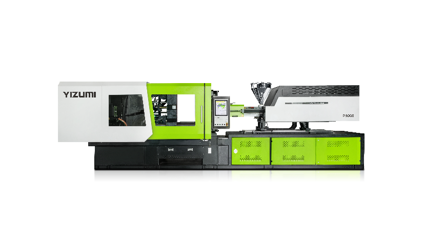
Strategic Partnership: Why Choose YIZUMI?
Choosing the right equipment is the foundation of repeatable quality
YIZUMI, a leading global manufacturer, provides solutions that prioritize stable shot consistency and rigid structural platforms to reduce scrap and improve uptime.
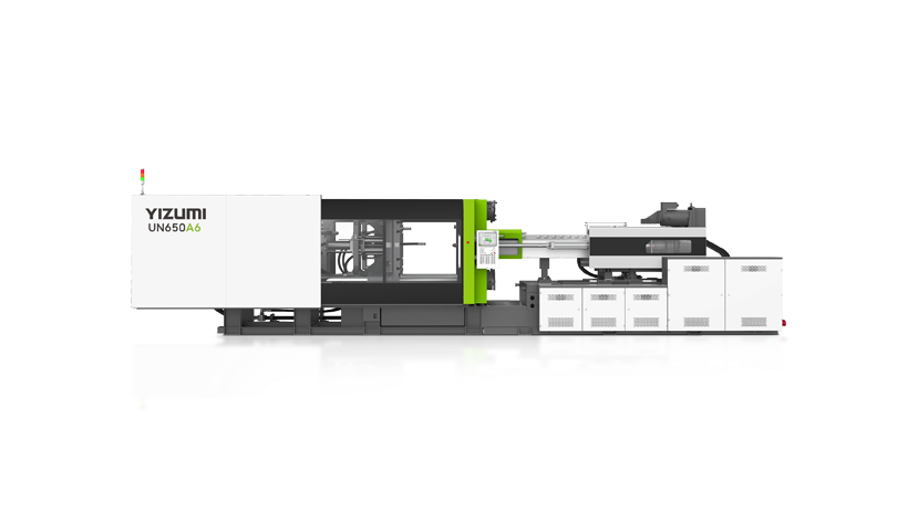
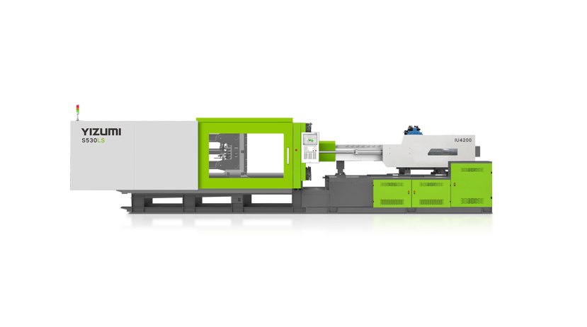
Diverse Product Series: YIZUMI offers high-end hydraulic models like the Next-Gen A6 and A5-EU series, as well as specialized machines like the DP Two-platen series and FF Electric series.
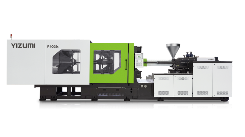
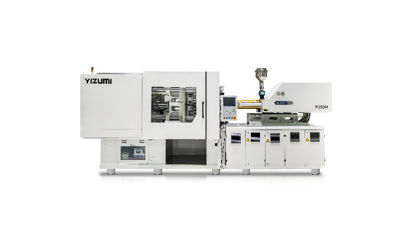
Energy Efficiency and Precision: The FF Series Electric Injection Molding Machines significantly reduce energy costs while offering higher precision and better compatibility with automation systems.
Specialized Applications: From Medical (FF-M) and Auto Parts to High-speed Packaging (PS5) and Thin-wall products (SJII), YIZUMI tailors machines to specific application fits.
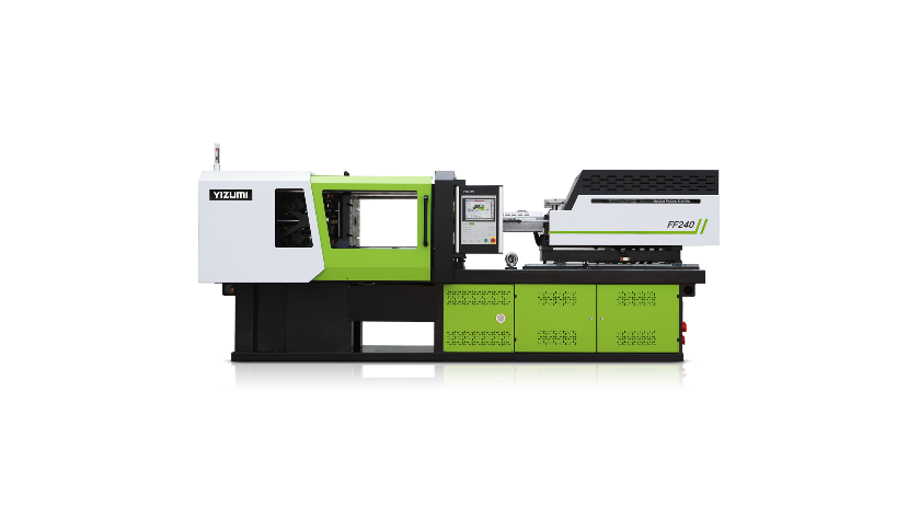
FF Series Electric Injection Molding Machine
Conclusion
Common injection molding machine problems are rarely as simple as they first appear. A short shot may be caused by poor venting. Flash may be the result of overpacking, not low clamp force. Burn marks may point to trapped gas, while dimensional drift may reveal machine wear rather than parameter error.
An effective approach is to look at injection molding as a connected system. Material behavior, mold design, process setup, and machine condition all influence each other. When processors troubleshoot with that broader view, they can solve problems faster, reduce scrap, improve consistency, and build a more stable production process over time.