Troubleshooting Liquid Silicone Rubber Injection Molding: A Comprehensive Guide
Abstract:
Troubleshoot liquid silicone rubber injection molding defects by tracing defects to root causes. Address short shots, flash, bubbles, sticky parts and premature curing through material delivery, mold venting, temperature, mixing and equipment checks.
Liquid silicone rubber molding problems rarely have a single cause. A short shot may begin with trapped air, but the underlying issue could be a blocked vent, an unbalanced runner, an unstable metering system, or premature curing near the injection point. Flash can come from process pressure, but it can also point to a worn parting line or poor mold alignment.
The most useful way to troubleshoot LSR is to work from the part defect back through the process. Start with what can be observed and measured. Then separate material, mold, machine, and process variables before changing a setting. This approach helps teams avoid repeated trial-and-error adjustments that solve one symptom while creating another.
Start With the Defect, Not the Machine Setting
Before adjusting temperature, pressure or speed, record the cavity number, defect location, material batch, part weight, start time and the most recent change to the mold or process. The pattern matters. A defect isolated to one cavity calls for a different investigation from a defect that appears across all cavities.
For safe and repeatable troubleshooting, stop the investigation and involve qualified process, mold or equipment personnel if there is damaged tooling, abnormal machine motion, an uncontrolled material leak, an overheating alarm or a safety-system fault. Do not bypass guarding, interlocks or approved operating procedures to keep production running.
| Visible issue | First checks | Avoid doing first |
| Short shot or underfill | Shot volume, last-fill area, venting, runner balance | Raising every pressure setting at once |
| Flash or backrind | Location of flash, mold parting line, shot consistency | Assuming clamping force is the only cause |
| Bubbles, blisters, stress whitening | Vacuum, vents, meter-mix air leaks, fill profile | Increasing injection pressure without inspection |
| Tacky or soft parts | A/B ratio, contamination, cure conditions | Increasing mold temperature before checking the mix |
| Flow marks, orange peel, scorch | Gate restriction, shear, cooling at the injection path | Changing material grade before process checks |
Rule: change one confirmed variable, produce a defined verification sample and compare it with the approved process window. A change that removes flash but creates underfill is not a stable correction.
Short Shots and Uneven Filling
A short shot occurs when LSR does not fully reach the end of the cavity. The part may be visibly incomplete, underweight, or show a small void at the last-fill area. In multi-cavity molds, some cavities may fill correctly while others do not.
Begin with three questions:
1. Is the issue present in every cavity or only selected cavities?
2. Is the material volume repeatable from shot to shot?
3. Can air escape from the last-fill area?
If only one cavity is affected, inspect the cavity-specific vent, gate, runner branch, and local mold temperature. If all cavities are short, review shot size, injection profile, metering performance, and any restriction in the cold runner or nozzle path.
Do not treat a short shot as a pressure problem alone. Higher pressure may temporarily fill the cavity, but it can also force air into the part or create flash elsewhere. A better sequence is to confirm material delivery, inspect venting, review the flow path, then make a small and documented change to injection speed or pressure.
For LSR, temperature control deserves particular attention. The material must remain processable through the injection path while the heated mold supports curing. Premature curing near the nozzle, static mixer, sprue, or cold runner can restrict flow and lead to inconsistent fill.
Flash, Backrind and Excess Trimming
Flash is thin silicone escaping at the parting line, vents, inserts, ejector locations or another shut-off surface. It increases finishing work and may affect the appearance, sealing function or dimensional requirements of the part.
The first diagnostic question is not whether to reduce pressure. It is where the flash is occurring.
· At the parting line: check fill level, mold alignment, shut-off wear, contamination and the uniformity of mold closure.
· At vents: confirm the vent condition and whether the process is overfilling the cavity.
· Around inserts or moving elements: inspect fit, alignment and wear; a mechanical clearance cannot be permanently corrected with a process setting.
Part weight is a useful control point. If weight varies, examine metering and injection repeatability before changing clamp or pressure settings. If weight is stable and flash repeats in the same location, prioritize a mold inspection. The objective is a repeatable process window, not a defect trade-off.
Bubbles, Blisters and Stress whitening
Air-related defects often appear at the last-fill area, in thicker sections or around complex geometry. They can present as internal bubbles, surface blisters, whitening or localized discoloration.
Inspect whether the vacuum and venting system is functioning as intended: seals, vacuum lines, vent surfaces and the timing of evacuation all matter. Then examine the meter-mix system and supply connections for possible air entry. If the defect follows a particular cavity, focus first on that cavity's venting and flow path.
Injection speed must be evaluated in context. A rapid flow front can prevent air from reaching the available vent path. Reducing speed across the entire fill phase can also create a new issue if curing begins before the cavity is complete. A staged fill study, supported by cavity-specific observations, provides a better basis for changing the relevant part of the injection profile.
Where venting requirements are demanding, vacuum assistance, mold design and the molding process should be assessed together. Vacuum is most effective when the parting-line seal, vent location, runner balance and routine mold maintenance are all controlled.
Incomplete Cure and Sticky Surfaces
A tacky surface, inconsistent hardness or sticking during demolding can indicate that the material, cure condition or local mold temperature requires investigation. Start with material identity, mixing accuracy and contamination control. Inspect supply lines, the static mixer and components that may carry residue from previous materials, adhesives, cleaning products or maintenance activities.
Then verify cure time and temperature uniformity across the tool. A local cold area, a thermally affected insert or an interruption in the production cycle can change curing and demolding behavior. More heat is not automatically the correct response: it can introduce premature curing near the gate or make another part of the process less stable.
Use the approved test method consistently when comparing hardness, dimensions or visual quality. A measurement that changes because the test method changed cannot confirm a process correction.
Follow a four-part diagnostic sequence
1. Confirm the pattern
Separate cavity-specific symptoms from part-wide symptoms. When only selected cavities are affected, inspect their vents, gates, runner branches, local heating and shut-off surfaces. When the defect occurs across the mold, begin with material delivery, injection behavior, machine condition and the common flow path.
2. Confirm material delivery and mixing
LSR processing depends on controlled delivery of its components through the metering and mixing system. Verify material identity, lot traceability, connection of the A and B components, additive feed where used, supply-line integrity and actual delivery behavior. The material supplier's technical data sheet remains the reference for the applicable mix ratio, storage conditions and curing profile.
Check the static mixer, feed lines, nozzle interface and seals whenever shot weight or part properties change unexpectedly. Air entry, residue or a developing restriction in these areas can create a defect that looks like a mold problem.
3. Inspect the mold as a flow-and-venting system
LSR remains processable through the injection path and cures in the heated cavity. This makes venting, temperature uniformity and the boundary between the cold and hot zones equally important. Review the last-fill area, vent condition, runner balance, gate restriction, parting surfaces, inserts and local temperature control as one system.
4. Adjust the process in small, traceable steps
Only after the material path and mold condition have been checked should the team adjust injection speed, pressure, hold profile, cure time or temperature. Record the original setting, the purpose of the change, the sample result and the decision to retain or reverse it. This creates a usable production history instead of a sequence of unrepeatable trials.
YIZUMI LSR Series: Product Advantages for Stable Liquid Silicone Molding
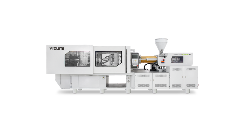
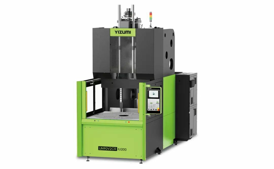
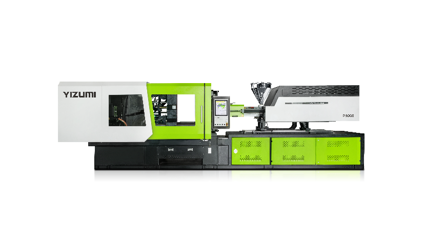
The YIZUMI LSR Series Liquid Silicone Injection Molding Machine is built for the material-handling and temperature-control requirements of liquid silicone rubber. Its core advantages target common process risks: premature curing, leakage, unstable feeding and temperature variation.
Key Product Advantages
· Water-cooled pneumatic injection nozzle: Helps prevent silicone leakage and limits mold-heat transfer to the nozzle, reducing the risk of LSR curing prematurely in the injection path.
· Silicone mixing screw and LSR-specific sealing rings: Blends A and B components at the front of the screw and helps reduce leakage during injection, supporting more consistent material delivery.
· Visualized mold temperature control: Provides direct temperature adjustment and separate connection sockets for each heating-unit set, making mold-temperature conditions easier to monitor and manage.
· Liquid silicone feeder: Uses pneumatic secondary metering and supports manual A/B ratio correction, with a stated ratio error of less than 3%. It is also designed to support uniform color mixing and repeatable feeding.
Which Defects Can These Features Help Investigate?
When pre-cured particles, unstable filling, leakage, incomplete cure or appearance variation occur, check the injection nozzle, mixing condition, material-feed path and mold-temperature condition before making broad changes to pressure or speed. Final settings should always be verified against the actual material, mold and product requirements.
YIZUMI's Strengths in the LSR Molding Industry
YIZUMI combines dedicated LSR injection equipment, liquid silicone feeding equipment and mold-temperature control with process and mold analysis, commissioning, process training and preventive maintenance support. The LSR Series serves applications including medical products, automotive parts, 3C electronics and high-speed packaging, helping manufacturers align equipment and process requirements with the part and production objective.
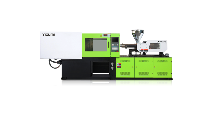
LSR Series Liquid Silicone Injection Molding Machine
Build Prevention Into Every Shift
The most effective troubleshooting happens before a reject trend becomes a production interruption. Include these checks in the process plan:
· Inspect vents and parting surfaces during scheduled mold maintenance.
· Verify material identity and A/B connection before startup.
· Record restart conditions after breaks or material changes.
· Review cavity-specific defects rather than only total scrap.
· Keep a verified process window and document every approved change.
· Escalate recurring defects with parts, photos, data, and machine history.
If a defect persists after material, mold, process, and measurement checks, prepare a technical review package rather than continuing random adjustments. Include the part drawing, mold layout, material data sheet, defect photos, cavity details, recent process records, and the actions already tested.
A structured investigation reduces wasted trials and gives the production team a clearer basis for deciding whether the next step is mold work, material support, process refinement, or an LSR equipment solution.